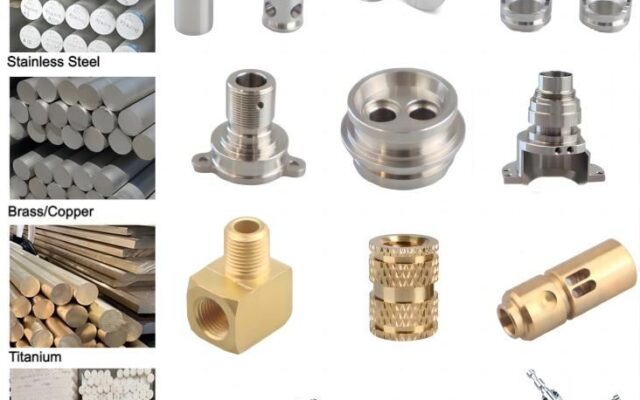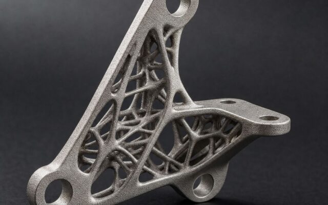

Before requesting a CNC quote, look at the part from the tool’s point of view. Check where the cutter enters, where the stock is held and how critical dimensions can be measured. A CAD feature that is easy to model can be hard to reach once the part is clamped.
Choose the process from the part’s geometry
For a shaft, sleeve or other shape defined mainly by diameters, start by reviewing CNC turning. For a plate or housing with pockets, flat faces and cross holes, start with milling. When a turned part also needs flats or off-axis holes, ask whether those features can be reached in the same setup or need a separate milling operation.
Mark the faces that must stay aligned and the features that require access from different directions. This lets the supplier evaluate workholding and whether a multi-axis setup makes sense for the geometry. Include the expected batch size because the practical fixture can change between a prototype and repeat production.
Check access and internal corners
A rotating milling cutter leaves a radius at an inside corner. If a square mating part has to fit into a pocket, review whether the mating part can be relieved or the pocket can use a local clearance feature. Where the corner does not control fit, allow a radius that gives the manufacturer room to choose a practical tool.
Review deep pockets and thin walls
A deep pocket with a small corner radius can force the use of a long, slender cutter. Tool deflection can affect finish and dimensional control. Consider widening the pocket or increasing its internal radius where the assembly allows. On thin walls, identify which faces are critical and leave room to discuss the machining and workholding sequence.
Flag features that affect machining and inspection
| Feature | What to check in CAD | What to put on the drawing |
|---|---|---|
| Blind drilled hole | Check access from the drilling direction and material remaining beneath the hole. | Specify the required full-diameter depth where it matters and clarify whether a drill point is allowed. |
| Blind threaded hole | Check room beneath the usable thread for tool clearance and chip evacuation. | Specify thread size, pitch and required full thread depth. Identify any coating or masking requirement. |
| Locating bore | Confirm the mating part and room for machining and inspection from the intended direction. | Call out the diameter and the location or alignment requirements that control fit. |
| Thin wall beside a pocket | Identify stock or faces the machinist can use for workholding and check clearance inside the pocket. | Mark the wall thickness and any surface or shape requirement that needs inspection after unclamping. |
| Features on opposite faces | Identify the faces that will locate the part if it is reoriented. | Reference related features to a consistent datum scheme where assembly depends on their alignment. |
Mark setup and inspection priorities
Group related features by the faces and datums that control assembly. On a mounting block, for example, the hole pattern and its position relative to the mounting face may matter more than a non-mating outside edge. Send both the model and the drawing with the same revision.
Worked example: a motor mounting plate
A motor locates in a pilot bore and bolts through a four-hole pattern. The mounting face seats against the housing. Mark the mounting face, pilot bore and bolt pattern as the functional features. Review whether the bore and bolt pattern can be cut from the same orientation, and identify the inspection setup that references the mounting face and locating feature.
If the outer profile clears the housing and has room around it, use the general tolerance where the design permits. Keep tighter controls on the pilot bore and bolt pattern where they affect fit. Add the finish and any areas that must be measured after coating. Ask the shop to report the bore and hole pattern on the first article if these features determine assembly acceptance.
CNC drawing release checklist
- Tool access: check that each hole, slot and pocket can be reached from a practical approach direction.
- Internal corners: check that the mating part clears the cutter radius, or identify exactly where a relief is needed.
- Deep pockets: mark the required depth and highlight any narrow entrances that restrict cutter access.
- Thin walls: identify walls that control fit and tell the machinist which faces can be used for temporary support or clamping.
- Setups: identify features that need to stay aligned across different machined faces.
- Datums: use reference features that reflect how the part is located in the assembly.
- Inspection: flag the dimensions to check and any report needed. Confirm that the model and drawing carry the same revision.
Explore the full CNC machining design guide and CNC milling service and capabilities.