Prototype Injection Molding Design Guide
Use prototype tooling to check fit, surface appearance, and part behavior in a relevant resin before scaling.
Get the Guide With Your QuoteValidate your part design with molded plastic prototypes made from production-relevant materials. Explore fit, function, appearance, and manufacturing feasibility before scaling up.
Overview
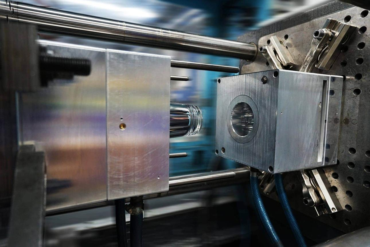
Prototype injection molding uses project-specific tooling to produce plastic parts for product development, design verification, and selected pilot builds. Unlike visual-only models, molded prototypes allow teams to evaluate parts made from the selected thermoplastic under more representative molding conditions.
It can help reveal issues related to fit, assembly, wall thickness, shrinkage, surface appearance, and material performance before production tooling and processes are finalized.
Tooling approach, material availability, lead time, and sample quantity depend on the part design and project requirements.
Use prototype tooling to check fit, surface appearance, and part behavior in a relevant resin before scaling.
Get the Guide With Your QuoteThe right tooling approach depends on part complexity, material, required quantity, expected production life, and validation objectives. We review these factors to help identify a practical route for
 Materials
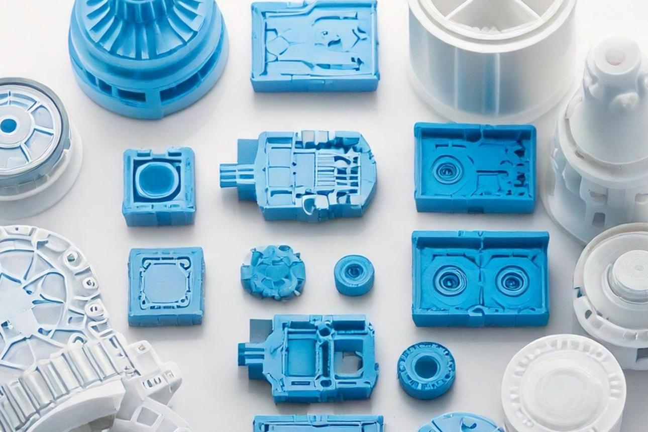
Material selection affects mechanical performance, molding behavior, appearance, and dimensional stability. BoValley can review the intended application and help identify suitable thermoplastics from the materials available for the project.
Depending on material availability and tooling requirements, prototype molding can use materials relevant to your intended production application.
| Parameter | Project Considerations |
|---|---|
| Process | Prototype injection molding |
| Tooling Approach | Selected prototype or low-volume tooling, subject to project review |
| Material Options | ABS, PC, PC/ABS, PP, PA, POM and other suitable resins, subject to availability |
| Part Size | Depends on mold dimensions, machine capacity, and part geometry |
| Wall Thickness | Often around 1–4 mm for many parts, but depends on resin, geometry, and performance requirements |
| Dimensional Accuracy | Depends on material shrinkage, tooling design, part geometry, and process control |
| Surface Finish | Depends on mold surface, resin, texture, and secondary finishing |
| Typical Quantity | Sample builds and selected low-volume runs |
The Process
1.Share Your CAD Files — Provide the 3D model and technical drawing. 2.Define Validation Goals — Specify material, quantity, color, texture, and functional requirements. 3.Review Tooling & Design — Evaluate the part design and suitable tooling approach. 4.Receive Your Quote — Confirm the proposed scope, cost, and lead time.
 Quality
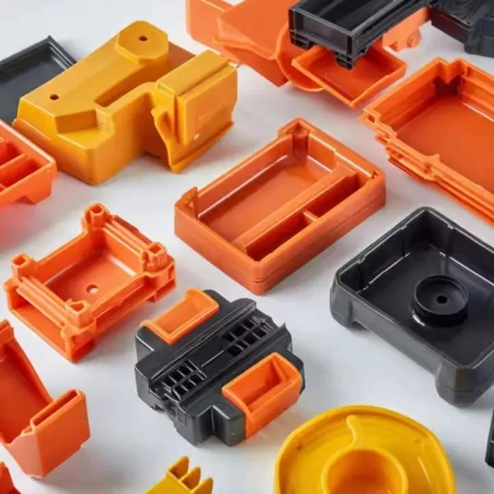
The examples below show where this process may fit. Material, geometry, and the intended use determine the right approach for each part.
Evaluate molded housings and covers for fit, appearance, and assembly.
Test interior parts and clips for fit and functional requirements.
Validate enclosure designs, mounting features, and component integration.
Assess robotics housings and mechanical interfaces before production tooling.
Evaluate plastic components and mounting features for assembly compatibility.
Test molded samples for fit and function before production release.
| Types of Parts | Function |
|---|---|
| Pilot housings | Check assembly fit and cosmetic appearance before committing to volume tooling. |
| Prototype clips | Evaluate fit and deflection in a representative resin. |
| Development covers | Compare finish and handling during a product trial. |
Upload your CAD file today — get a detailed quote with DFM feedback within 24 hours.