
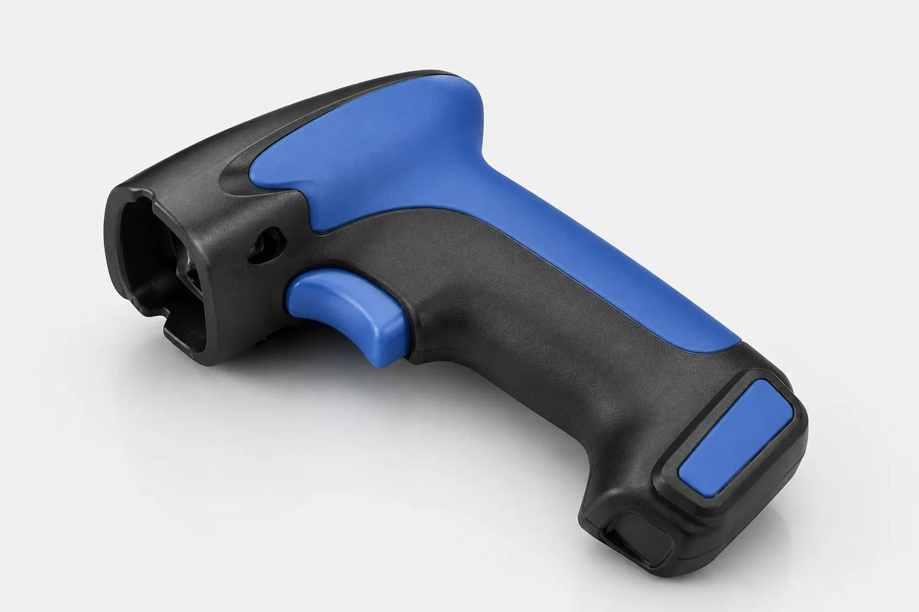
Overmolding Design Guide
Select the substrate and overmold as a pair, then review bonding, edge transitions, and mechanical retention.
Get the Guide With Your QuoteBoValley provides overmolding solutions that combine compatible materials in a single integrated component. By molding a secondary material over a preformed substrate, overmolding can improve grip, comfort, sealing, and product functionality while reducing the need for separate components and assembly steps.
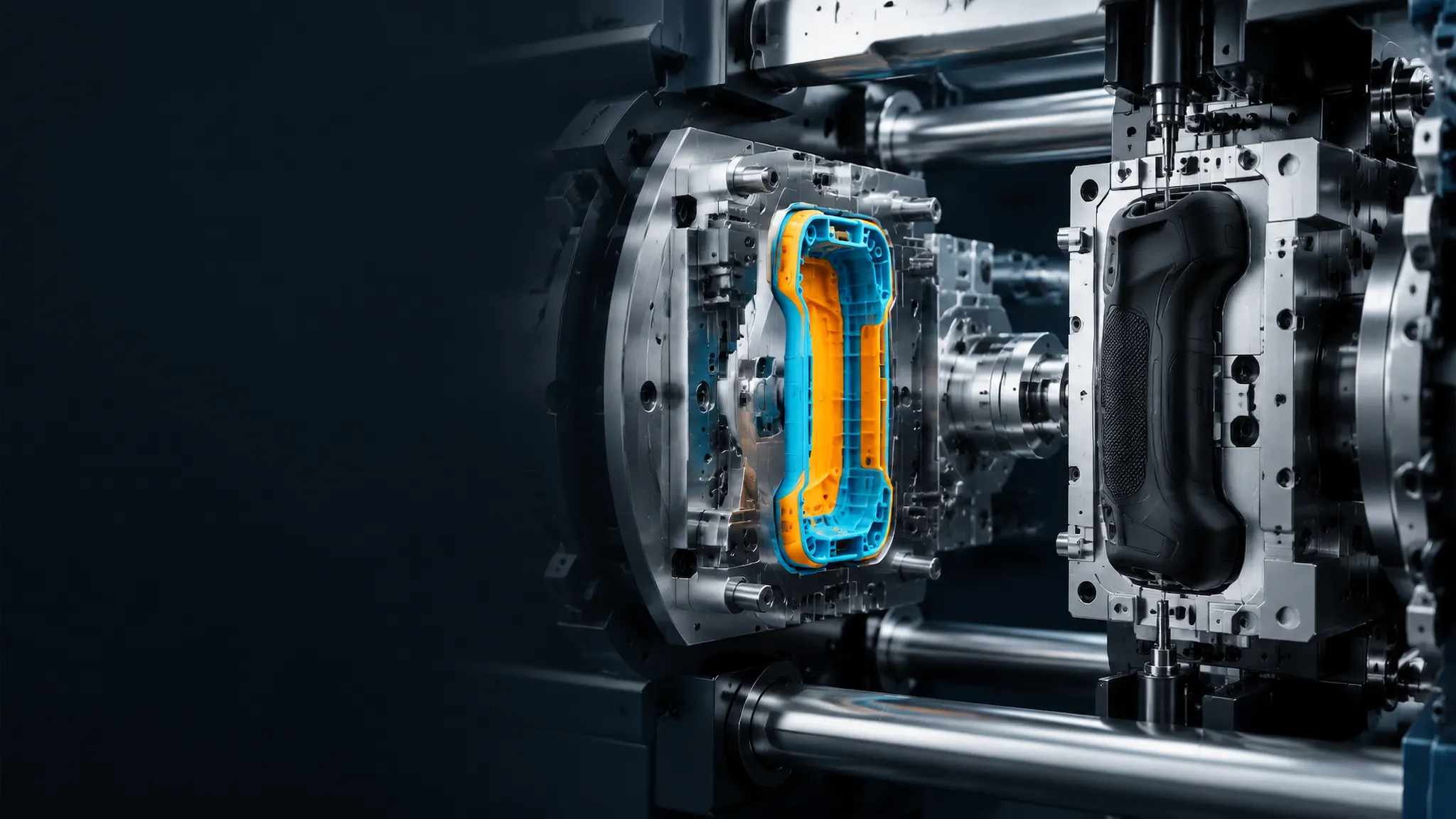
Overview
Overmolding is an injection molding process in which one material is molded over a previously formed component, known as the substrate. The substrate may be a rigid plastic part or, in some applications, a metal component.
A secondary material—often a thermoplastic elastomer (TPE) or thermoplastic polyurethane (TPU) —is molded over selected areas of the substrate to create a combined part with different surface or functional properties.
Successful overmolding depends on substrate design, material compatibility, surface preparation, mold design, and process control. Chemical bonding may be possible with compatible material combinations; mechanical interlocking may be needed for others.
Select the substrate and overmold as a pair, then review bonding, edge transitions, and mechanical retention.
Get the Guide With Your QuoteOur basic guidelines for Overmolding include important design considerations to help improve part moldability, enhance cosmetic appearance, and reduce overall production time.
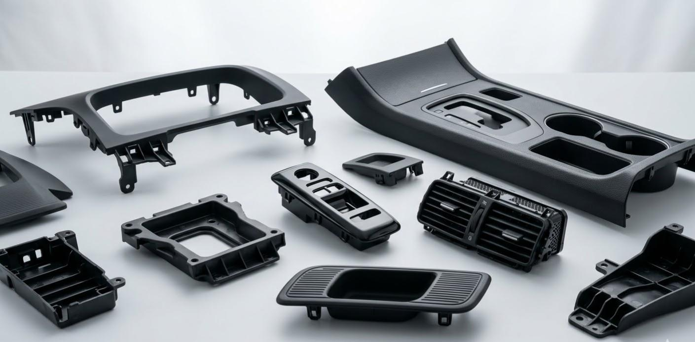 Materials
Material selection depends on the substrate, desired feel, bonding requirements, operating environment, and production process. The examples below represent common categories, not a guarantee that every combination is available.
Choose materials and finishes based on your part's mechanical properties, operating environment, appearance, and application requirements.
| Parameter | Typical Options / Considerations |
|---|---|
| Process | Overmolding onto a preformed substrate |
| Substrate | Compatible rigid plastics; selected metal substrates where appropriate |
| Secondary Materials | TPE, TPU, and other compatible materials subject to availability |
| Bonding Method | Material-to-material bonding, mechanical interlocking, or a combination |
| Hardness | Selected by application and available material grade |
| Part Geometry | Grip areas, soft-touch zones, seals, protective layers, and selected interfaces |
| Tooling Approach | Insert loading, transfer between mold stages, or dedicated multi-stage tooling |
| Quality Checks | Interface integrity, appearance, dimensions, and application-specific testing |
| Production Volume | Prototype tooling or production tooling, depending on project requirements |
The Process
01. Substrate Design Review: Review the base part, bonding areas, locating features, and material compatibility. 02. Mold and Material Planning: Define the substrate positioning, secondary material, gate locations, and overmold geometry. 03. Secondary Material Molding: Mold the secondary material over the substrate using a suitable process and tooling arrangement. 04. Bonding and Part Inspection: Inspect appearance, material interface, dimensions, and specified bonding or functional requirements.
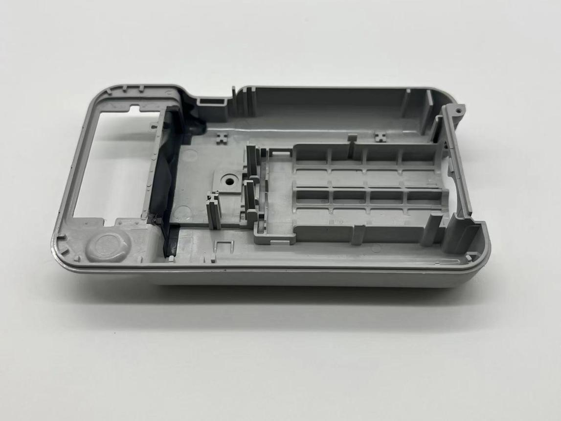 Quality
The examples below show where this process may fit. Material, geometry, and the intended use determine the right approach for each part.
Grips for tools and consumer products.
Soft-touch or cushioning features.
Selected integrated seals and interfaces.
Two-material designs combining appearance and functionality.
laboratory product development components, subject to material and compliance requirements
handles, knobs, and operator interfaces
| Types of Parts | Function |
|---|---|
| Tool grips | Add a compliant handling surface over a rigid core. |
| Sealing interfaces | Integrate a flexible contact region into a rigid part. |
| Protective bumpers | Add a resilient exterior where the substrate needs impact protection. |
Upload your CAD file today — get a detailed quote with DFM feedback within 24 hours.