Why DFM Review Changes the Price
Two parts with the same bounding box can differ by a factor of three in price. The difference is almost never the material — it is the number of setups, how many tools a feature needs, how many times the part has to be repositioned, and how much of the geometry has to be inspected afterwards. Design for manufacturability (DFM) is the practice of deciding those things while they are still free to change.
At BoValley every quote includes DFM feedback, because a five-minute geometry change in CAD can remove an entire setup from the shop floor. The rules below cover the comments we raise most often on CNC programs.
Rule 1: Design Internal Corners Around the Cutter
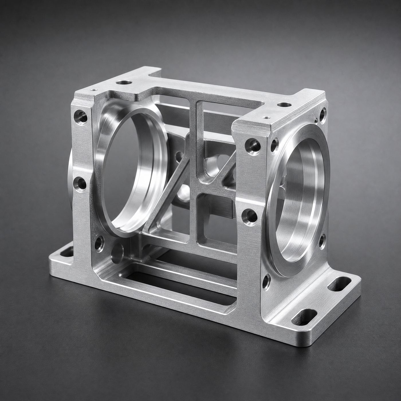
A rotating cutter always leaves a radius equal to its own radius. If a drawing calls for a sharp internal corner, the shop has three choices: leave the largest possible radius, cut the corner with a smaller tool in a second operation, or burn it out with EDM. All three cost more than designing the radius in.
- Standard practice: internal corner radius ≥ 1/3 of pocket depth.
- A 6 mm end mill leaves a 3 mm corner — call out R3, not R0.5.
- For deep pockets, specify the largest radius the function allows, then add a relief if a mating part needs to sit flush.
- Add a small corner relief instead of a sharp corner when a square mating feature is unavoidable.
Rule 2: Control Depth-to-Diameter Ratio
Deep, narrow pockets force long, thin tools that deflect. The result is chatter, poor finish and extra finishing passes. Keep pocket depth under roughly four times the cutter diameter, and open up the entry so the tool can reach the floor without rubbing.
| Feature | Comfortable | Needs review | Costly |
|---|---|---|---|
| Pocket depth : width | up to 4 : 1 | 4 : 1 to 8 : 1 | over 8 : 1 |
| Bore depth : diameter | up to 4 : 1 | 4 : 1 to 10 : 1 | over 10 : 1 |
| Wall thickness (metal) | ≥ 0.8 mm | 0.5–0.8 mm | under 0.5 mm |
| Floor thickness | ≥ 1.0 mm | 0.5–1.0 mm | under 0.5 mm |
Rule 3: Tolerance Only What Functions
A blanket tolerance note such as “all dimensions ±0.025 mm” is the single most expensive habit in mechanical drawings. It converts a part with four critical dimensions into a part with forty, and every one of them has to be measured and defended.
- Use ISO 2768-medium as the general note — it covers most non-critical geometry.
- Call out tight tolerances only on mating, sealing, bearing and alignment features.
- Remember that ±0.005 mm is achievable, but only with review, fixturing and inspection time.
- Prefer geometric callouts (position, flatness) over linear tolerances where they express intent better.
Rule 4: Minimise Setups and Operations
Every time a part moves to a new fixture, cost and error stack up. Design so that the maximum amount of geometry can be reached from one direction, and keep secondary operations off the critical path.
- Five-axis access is available, but 3-axis from two sides is often cheaper than 5-axis contouring.
- Avoid features on faces that are hard to clamp — think about how the vise grips the part.
- Standardise threads and hole sizes so the same tools cover more of the part.
- Group multiple small parts into one blank as a family tool when volumes are low.
Rule 5: Choose Finish Where It Is Seen
As-machined finish is a functional finish. It is deburred, dimensionally correct and uniform enough for internal parts. Cosmetic finishes such as bead blasting, anodizing or polishing add per-part cost and, in the case of anodize, can shift dimensions slightly.
If only one face is visible to a customer, say so on the drawing. We can finish that face and leave the rest as machined, which keeps both the price and the schedule realistic. For a full list of options see surface finish options.
Rule 6: Give the Shop the Information It Needs
Most delays in CNC programs are not machining problems, they are information problems: a STEP file without units, a thread callout that contradicts the model, a finish note that names no standard. A complete request looks like this:
- 3D CAD in STEP or IGES plus a 2D drawing for tolerances and callouts.
- Material and temper, not just “aluminum”.
- Critical dimensions marked, with the rest covered by a general tolerance.
- Finish standard (for example SPI, Ra value, or coating specification).
- Inspection requirements: what documentation needs to ship with the parts.
A Quick Worked Example
A customer sent a sensor housing with a 60 mm deep, 20 mm wide pocket and sharp internal corners. The original design required a second setup with a long 3 mm cutter and a hand deburr of the corner. After DFM review the pocket was opened to 24 mm with R4 corners and a 12 mm relief at the base. Machining time dropped by about 35 percent, the second setup disappeared, and the part still sealed against the same gasket.
That is what DFM is worth: not a nicer drawing, but a cheaper part that still does its job. See the full CNC machining capabilities page for tolerances, envelope sizes and materials.