Design a printed part around the test you need to run. A presentation model, a working latch and a shop fixture may need different materials, print orientations and finishes. Decide which features need to look right, carry a load or fit a mating part before choosing the process.
Choose a process based on what the part must do
Decide which property matters most for the next test. A presentation model may need fine detail and a smooth surface. A functional housing may need snap retention, impact resistance or an accurate fit after finishing. Give the supplier the load direction, visible faces and mating dimensions so the build can be planned around them.
| Process | Typical reason to evaluate it | What to confirm before release |
|---|---|---|
| FDM | Early fit models, shop fixtures and thermoplastic prototypes. | Layer direction, bridge or overhang support, and how supports will be removed from critical surfaces. |
| SLA | Fine features, visible detail and parts made with a specific photopolymer. | Support contact points, resin and wash access, and final dimensions after the required cure. |
| SLS | Functional polymer parts with complex geometry. | Powder escape and cleaning access, especially for enclosed features and moving assemblies. |
| MJF | Functional polymer parts and repeat batches. | Wall stability, access to remove powder and the dimensions that must be checked after finishing. |
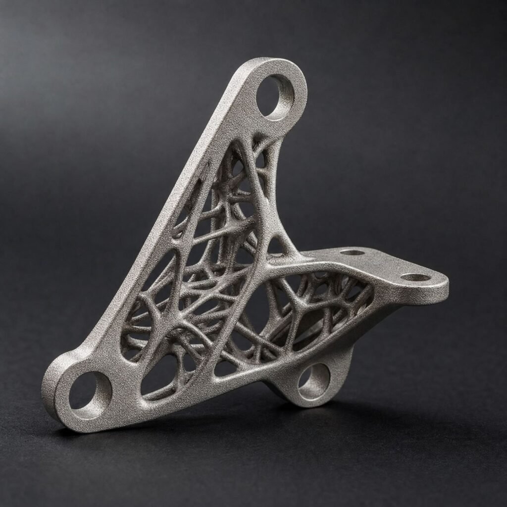
| Metal powder bed fusion | Metal parts whose geometry is difficult to machine conventionally. | Support removal, access for powder removal, and allowances for heat treatment or machining on functional faces. |
Plan for the way the part is built
SLA uses cured resin and often needs support contact on some surfaces. Mark cosmetic areas and allow access for cleaning and curing. In FDM, the layer direction can affect strength. Discuss how the part should be oriented for the main load and where supports can be removed.
Allow access to remove powder and supports
SLS and MJF build parts in a powder bed. The surrounding powder supports many shapes during printing, but trapped powder still needs a way out. Review openings and cleaning access for enclosed cavities and internal channels. In a design with a movable joint, check both clearance and the route for removing powder.
Specify walls, holes, clearances and finish as a set
- Walls and ribs: share the thinnest wall, its height and whether it is supported along an edge. Ask for the process and material limits for that geometry. A long unsupported wall may need a rib or more thickness.
- Holes and channels: specify finished diameter and required access. For a small bore that controls alignment, discuss printing a pilot feature and drilling or reaming it afterward.
- Threads and inserts: identify whether the feature is for a fit trial, repeated assembly or load transfer. Discuss printed threads, tapped holes and inserts with the supplier based on the material and available wall thickness.
- Clearances: state the required movement or fit after curing, cleanup and finishing. Check test samples made with the intended build orientation and material.
- Appearance: mark visible faces and explain what surface marks are acceptable. Keep support contact or cosmetic finishing away from mating surfaces where possible.
Machine and material limits vary. The Formlabs SLA design specifications and HP MJF design guidance illustrate the kinds of limits and cleanup access to confirm for a selected process.
Example: a sensor enclosure with a sliding lid
Consider a small sensor enclosure with a sliding lid, guide rails and an internal cable passage. The lid needs to slide smoothly after finishing, and the passage needs to be clear before wiring.
- FDM: Orient the housing so the rails can be printed cleanly. Keep supports reachable so they can be removed without leaving ridges on the sliding faces.
- SLA: Where possible, place support contacts away from the mating faces. Give uncured resin and wash fluid a path out of the cable passage.
- SLS or MJF: Give the passage accessible openings for powder removal. Review how powder will be cleared from the rail grooves and check that the passage is clean before fitting the cable.
Print short samples of the mating rail and lid at several candidate clearances using the planned material, build orientation and finish. Measure the mating widths and try each fit after cleanup. Confirm the chosen clearance on a full-size enclosure before ordering the batch.
Validate the features that need to work
Mark thin walls, clips and other details that may be sensitive to the selected material or build orientation. Specify mating dimensions and check them with a test print before ordering a batch. If a bore or mounting face needs a tighter fit, discuss finishing or machining it after printing.
Release the model with a validation plan
- Send the model and confirm its units. Include a drawing for critical dimensions, flatness, threaded inserts and any machining after printing.
- Mark load directions, cosmetic faces, mating features and areas that must stay clear of support marks. Describe the material, finish and expected environment.
- Agree on how the part will be cleaned and measured. For functional joints, test motion or assembly after all planned finishing steps.
- Record the approved process, material, orientation and finish with the first article so repeat builds use the same agreed conditions.
Use the 3D printing process directory to compare the available process options.
Explore the 3D printing process options and SLS for functional nylon parts.