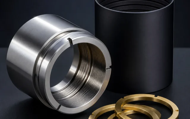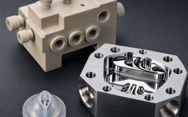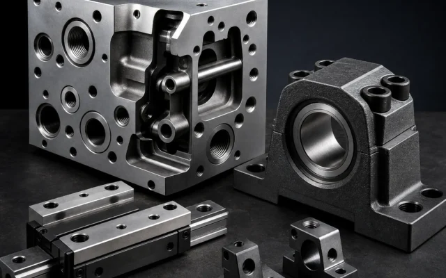

High-Dynamic Motion, Compact Actuation & Industrial Automation
From multi-axis CNC machined articulated robot arm joint links to bionic humanoid actuator skeletons and high-torque autonomous mobile robot (AMR) drive hubs — BoValley manufactures high-precision, high-rigidity robotics components engineered for extreme repeatability and dynamic payload control.
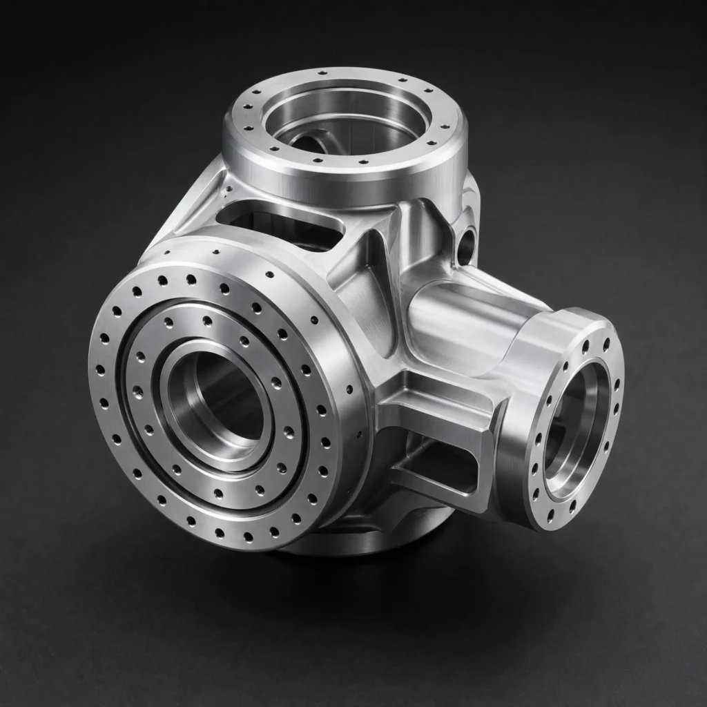
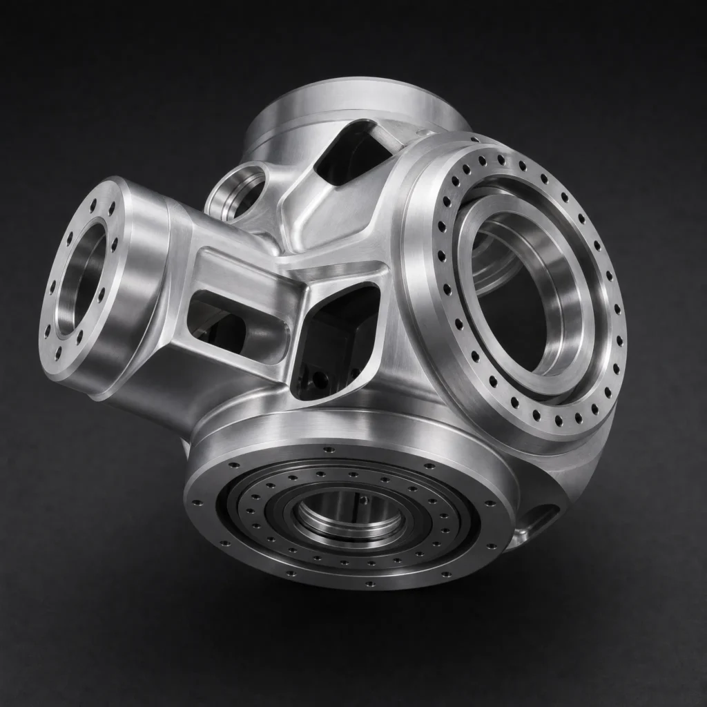
Case 01 | 6-Axis Robot Arm Joint Link (Harmonic Drive Integrated Housing)
Multi-Angle Visual Gallery

1. Manufacturing Process & Material Selection
- Core Process: 5-Axis Simultaneous CNC Machining (Single-clamping dual-bore boring) + High-Speed Adaptive Trochoidal Milling + Shot Peening + Satin Anodizing with Corrosion Sealing (Type II, Natural Silver / Slate Grey).
- Material Grade: Aviation-Grade High-Strength Aluminum Alloy 7075-T6 / 6061-T6
- Engineering Justification: Ultra-high strength-to-weight ratio to minimize joint arm inertia, high elastic modulus (≈71 GPa) to prevent dynamic deflection under sudden deceleration stops, and superior machinability.
- Tolerances & Precision: Harmonic drive pilot locating diameter tolerance held to H7 +0.012/−0 mm; dual orthogonal axis perpendicularity ≤0.008 mm;bearing seat runout ≤0.005 mm.
2. Structural Features & Manufacturing Challenges
- Orthogonal Dual-Axis Bore Alignment (Perpendicularity & Concentricity):
- Challenge: The joint link translates rotational motion across two intersecting axes (90°orthogonal). Any angular deviation between the input drive bore and output pivot bore causes internal gear binding, accelerated backlash wear, and robotic positioning drift.
- Solution: Utilized a high-precision 5-axis horizontal machining center with an optical direct-drive rotary table. Both orthogonal bearing bores were line-bored in a single setup without reclamping, using customized micro-adjustable digital boring heads.
- Thin-Wall Hollow Architecture with Integrated Wiring Ducts:
- Challenge: To route internal power, encoder,and Ethernet harnesses, the internal arm cavity is deeply hollowed with wall thicknesses down to 2.2 mm, creating chatter vibration risks during high-speed peripheral milling.
- Solution: Deployed variable-helix carbide end mills and programmed adaptive chip-thinning toolpaths, applying vibration-absorbing internal polymer support fixtures during exterior finish profiling.
3. Real-World Applications
- 6-DOF Industrial Collaborative Robots (Cobots, 5 kg–20 kg Payload): Serving as the J2/J3 elbow and shoulder joint structural links, housing frameless torque motors and strain-wave harmonic reducers.
- Precision SCARA & Delta Pick-and-Place Arms: Providing high-torsion structural linkages in high-speed electronics assembly lines.
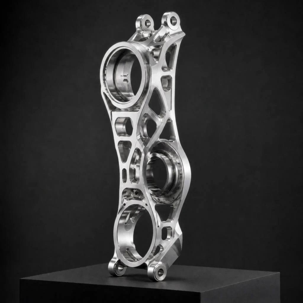
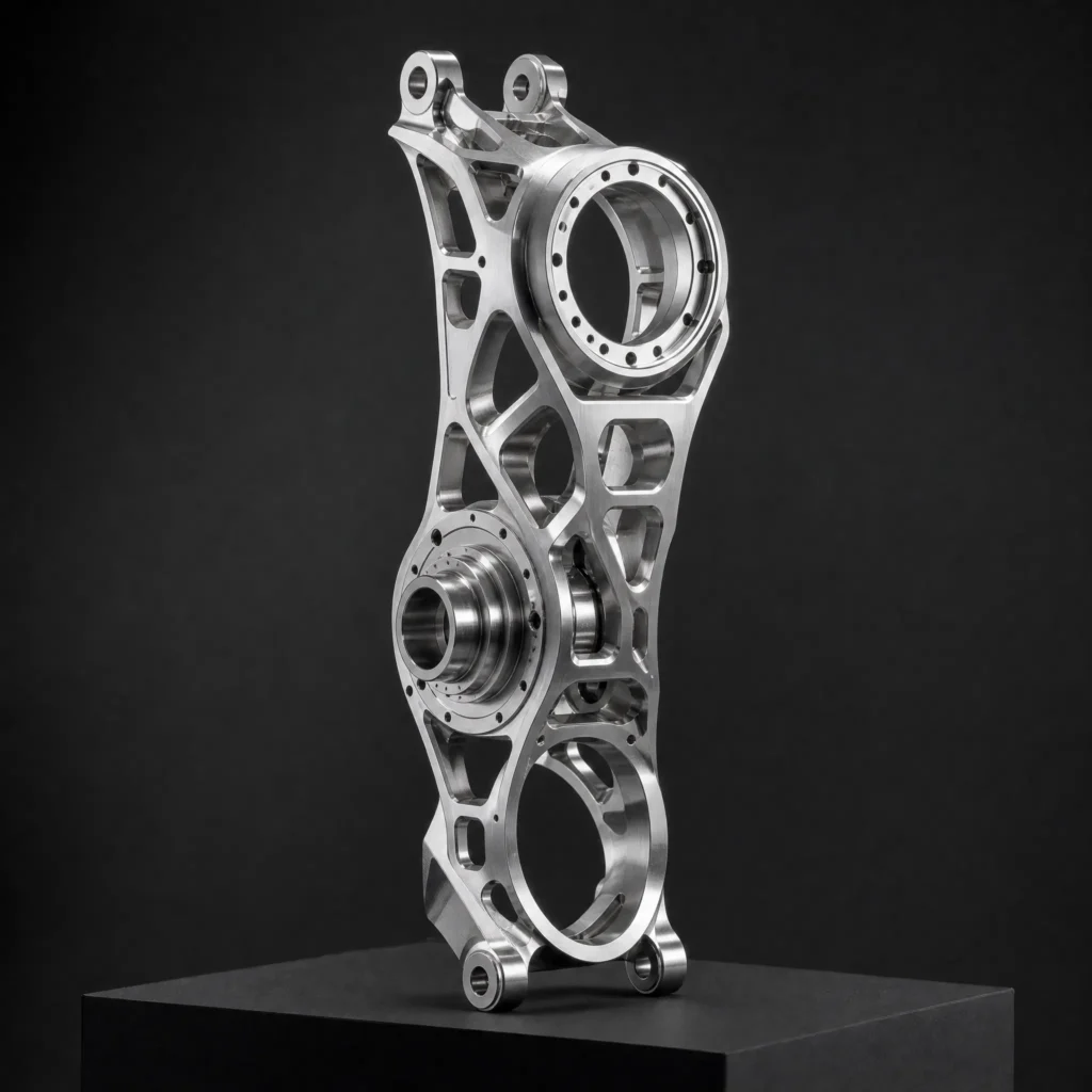
Case 02 | Humanoid Robot Bionic Actuator Bracket (Knee & Ankle Dual-Axis Frame)
Multi-Angle Visual Gallery
1. Manufacturing Process & Material Selection
- Core Process: High-Speed 5-Axis CNC Milling Center (Micro-Machining Capability) + Stress-Relief Cryogenic Annealing + Ultra-Fine Bead Blasting (220#) + Micro-Arc Oxidation (MAO) / Hard Anodizing.
- Material Grade: Aviation Titanium Alloy Ti-6Al-4V (Grade 5) / High-Purity 7075-T651 Aluminum
- Engineering Justification: Maximizes power density by stripping away non-load-bearing mass. Provides extreme impact fatigue resistance and high fracture toughness against dynamic foot-strike ground reaction forces.
- Tolerances & Geometry: Frameless motor stator press-fit bore tolerance held to ±0.005 mm; planetary carrier concentricity ≤0.006 mm; pivot hinge pin alignment ≤0.008 mm.
2. Structural Features & Manufacturing Challenges
- Organic Curvilinear Topology Optimization with Deep Undercuts:
- Challenge: The generative organic lattice structure mimics biological bone trabeculae with complex non-standard 3D freeform surfaces, presenting severe tool access limitations and chatter along variable-thickness ribs (1.5 mm).
- Solution: Developed 5-axis continuous multi-surface finishing routines using high-speed micro ball-nose cutters. Tool axis vectors were continuously oriented along normal surface tangents with collision-avoidance look-ahead algorithms.
- Zero-Backlash Bearing Pilot Concentricity:
- Challenge: The actuator integrates planetary reducers and high-resolution absolute magnetic encoders; any radial eccentricity causes motor cogging, torque ripple, and sensor signal distortion.
- Solution: Performed finish diamond-boring on thermal-stabilized machines with spindle chiller control, validated by in-process touch-probe feedback before part release.
3. Real-World Applications
- Bipedal Humanoid Robot Lower-Limb Actuation: Serving as the structural core of the knee flexion/extension and ankle 2-DOF roll/pitch actuator modules.
- Medical Powered Exoskeleton Rehabilitation Suits: Bearing patient body weight while housing brushless DC motors and strain-gauge torque sensors.
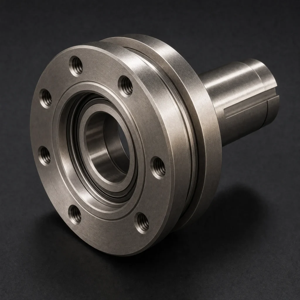
Case 03 | Autonomous Mobile Robot (AMR / AGV) Heavy-Duty Drive Hub & Flange
Multi-Angle Visual Gallery

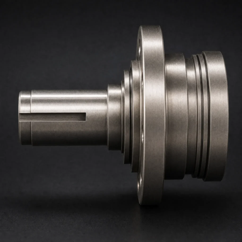
1. Manufacturing Process & Material Selection
- Core Process: Multi-Spindle CNC Turn-Mill Compound Center + Induction Case Hardening (HRC 52–56 on bearing journal) + High-Precision CNC Cylindrical OD/ID Grinding + Electroless Nickel Plating (ENP,15–20μm).
- Material Grade: High-Tensile Alloy Structural Steel 4140 / 42CrMo4 (Quenched & Tempered)
- Engineering Justification: High torsional fatigue strength, excellent core toughness, and deep hardenability, withstanding intense dynamic shock loads, curb impacts, and continuous heavy-payload wheel torque.
- Tolerances & Dimensions: Bearing journal cylindrical diameter tolerance held to m5 +0.009/+0.004 mm; wheel mounting flange radial/axial runout ≤0.006 mm; ground bearing seat surface roughness Ra 0.2 μm.
2. Structural Features & Manufacturing Challenges
- Heavy Radial Load Bearing Shoulder & Shaft Runout Control:
- Challenge: Stepped shafts with multiple diameter transitions easily develop concentricity runout errors when turned and ground across multiple setups, leading to premature bearing spalling under 1-ton payloads.
- Solution: Turn-mill compound machining executed all OD steps, face grooves, and milled keyways in a single continuous clamping chucking. Bearing journals were subsequently finished on a CNC cylindrical grinder using hydrostatic centers.
- Integrated Labyrinth Contamination Seal Machining:
- Challenge: Warehouse and outdoor AMR environments expose wheel hubs to fine dust and moisture. The hub incorporates precision multi-groove non-contact labyrinth seals with micro-recessed interlocking lips.
- Solution: Micro-grooving tools cut exact radial tooth profiles, followed by electroless nickel plating (ENP) to provide anti-friction corrosion protection without dimensionally clogging seal clearances.
3. Real-World Applications
- Warehouse Logistics Autonomous Mobile Robots (AMRs, 500 kg–1500 kg Payload): Integrated into dual differential drive units and omnidirectional Mecanum drive modules.
- Heavy-Duty Automated Guided Vehicles (AGVs) & Port Automated Transporters: Transferring heavy powertrain and battery pack transport payloads in smart gigafactories.
See the processes, materials and inspection considerations for robotics manufacturing at BoValley.